Concepts
Tribli is a convenience application that attempts to automate the application of the tributary area method for the calculation of gravity loads in multi-storey buildings. Critically, the structural information can be input via the use of a PDF markup, where the markups represent discrete structural elements (slabs, columns, beams, areas loads etc.). Once the structural data has been imported via PDF or other methods, Tribli provides a multitude of functions to design, analyse and export the data into various formats. Tribli is not a black box, and the user should take great care to ensure that the input information is applicable for the methods used by Tribli, as outlined in this document. The user must exercise engineering judgement when determining whether the program inputs and outputs are suitable for their purposes.
Definitions
- Column – A column as defined within this document, and more broadly within Tribli, is a load-bearing structural member that exists at a single level only, running from that level to the level below. A column’s location is defined by a single point in 2-dimensional space. Columns are unnamed.
- Column Chain – A column chain is a string of columns that pass load from one level to the next, down the structure. Column chains must be continuous through all levels between their uppermost and lower-most levels. Columns within a column chain do not necessarily need to be aligned in their position from one level to the next, they will receive the cumulative building loads passed down from the column at the level above purely by being assigned to the same column chain. Column chains are either manually or automatically assigned names and no two chains may possess the same name. In addition to a column at each level, a column chain may have a single footing assigned at the level below the level of the lowest column in the chain.
- Wall - A wall as defined within this document, and more broadly within Tribli, is a load-bearing structural member that exists at a single level only. A wall’s location is defined by a line segment in 2-dimensional space. Walls are unnamed.
- Wall Chains – Wall chains behave in exactly the same manner as column chains, but with wall elements. Wall chains cannot have the same name as any other wall or column chain.
- Orphans – A Column or Wall element that is not assigned to any chain is referred to as being ‘Orphaned’. Orphaned elements can have tributary areas and attract load, but do not pass this load on to any element beneath them. The user should therefore avoid orphaned elements in order to prevent load losses in the structure.
- Shear Throw - A modifying factor applied to loads generated via the tributary area method to account for the effects of slab continuity
Column and Wall Graphics
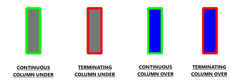
Column and wall elements displayed in Tribli are colour-coded to easily identify key information about each element. All elements under are displayed with a grey fill, whereas elements over are displayed with a blue fill. A red outline indicates that the element is the lowest element in the column or wall chain that it is assigned to, meaning that the element must either found at the current level, or be transferred out. A green outline means that there are elements within the same chain supporting the displayed element.

Wall element colours are the same as columns, however the outline is dashed.
Orphaned elements will appear with an orange outline.
Tributary Areas
Tribli uses the tributary area method to calculate column and wall loads. This method can be extremely powerful, but by its nature is an approximation of the final column loads only. Tribli uses Voronoi diagrams to generate tributary areas. This results in mathematically perfect tributary area shapes, where each tributary area represents the region of space that is closer to the column or wall in question than to any other column or wall. However these mathematically perfect areas may not always accurately represent the behaviour of the structure and the appropriateness of their shape should be assessed by the engineer and if required, altered using the methods outlined below.
Modifying Tributary Areas
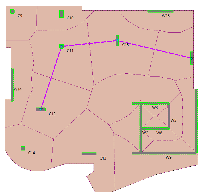
Tributary areas may be modified directly by activating the Edit Trib Areas option in the edit menu or via the use of tribline elements. Triblines behave similarly to how one would consider a beam behaving, by attracting tributary area to themselves, then passing that load back to a load bearing element. Triblines attract load in the same way that a wall element does in that they are broken down into a series of discrete points based in their ‘resolution’ property and a tributary areas is calculated for each individual point, before being merged back into a single shape. Any time a tribline passes by a column or crosses a wall, it will add a portion of its tributary area to that element. The portion of tributary area given to a particular column or wall is equal to the area attracted by the tribline between the location of the element and a point halfway between that element and the next column/wall to which the tribline applies tributary area. A visual illustration of the use of triblines can be seen in the image below, where the tribline is shown as a dashed purple line.

Limitations of the Tributary Area Method
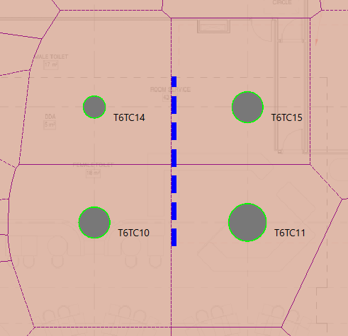
Tribli works by calculating a ‘tributary area’ for each column, then looking at portions of the applied loads that fall within this area and applying them to the given wall or column. This method is simple, yet quite effective for broad, distributed loadings. It does, however, have its shortcomings when considering more concentrated loads, such as line loads. Take the image below for example, the line load is applied approximately midway between the left and right column line, we would therefore expect that the load would be distributed roughly in half between the two column lines. The arrangement of the tributary areas in this example however, although correct, results in all of the load being applied to the right-most columns, and none to the left-most. This is obviously not the desired outcome. It is expected that the user will format their model in such a way that prevents situations like this from occurring (in this instance, the line load could be split in two and placed either side of the tributary area boundary).

Point loads are not possible when using the tributary area method, and thus are not available in Tribli. It is however possible, to specify additional manual dead and live loads for each column in the column properties dialog, although note that these loads are only updated when the full model loads are recalculated.
Shear Throws
Tribli employs shear throw factors as a mechanism to account for slab continuity effects that are not considered by the underlying tributary area method. Each column and wall element has a unique shear throw factor that increases or decreases the load received by that element due to its position within the structure. For instance, edge and corner columns may only receive 80% of the load that would be expected from the unmodified tributary area method, whereas internal columns may receive 120% or more of the expected load.
As a simple analogue of this phenomenon, imagine a two-span continuous beam with two 10m spans under a uniform load of 1kN/m. Based on a tributary area (width) method, we would expect the reactions at the two outer supports to be 5kN each and 10kN at the centre support. If we instead use a finite element method to assess this beam, we see that the outer reactions are 3.75kN and the inner reaction 12.5kN. In this situation, shear throw factors of 0.75 and 1.25 could be used to correct the exterior and interior supports respectively.
By default, Tribli truncates automatically calculated shear throw values such that no shear throw is less than 1.0. This allows for non-ideal behaviour of the slab (caused by inadequate hogging reinforcement over the first internal column for instance) and for pattern live loading effects, however may be considered excessively conservative in some situations. The user may adjust the shear throw floor prior to calculating shear throws.
Shear throw factors can be manually modified in the column and wall properties dialogs, otherwise Etabs or RAM Concept may be used to estimate the shear throw factors automatically.
Superposition
Unlike many other engineering software packages, Tribli operates on the principal of shape superposition, where overlapping polygonal objects have their effects summed together during analysis. This means that two overlapping slabs, each 200mm thick, will effectively behave as a 400mm thick slab when calculating the slab dead load. The same is true of area loads. This principal can also be used with negative loads and slab thicknesses to subtract loading from the underlying slab. For instance, to model 30mm wet area set-downs in a 200mm thick slab, the user could simply model outline of the slab, then draw additional slabs in the wet areas with a thickness of -30mm.
Some functions in Tribli (SAFE exports for instance) must convert from this superimposed state to a more traditional state where no overlapping polygons are allowed. This conversion process can result in long slithers of slab if the slabs are not adequately snapped together and may result in errors, either within Tribli or within 3rd party software to which the user is attempting to export data.
The above said, it is recommended that the user avoid the use of overlapping slab elements in order to provide clarity to users unfamilar with Tribli and to improve the robustness of import/export functions.
Transfers
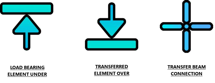
Transfers in Tribli are accomplished by specifying the percentage of each transferred column or wall load that should be transferred to a specified element below. The percentage transfers for a given element should sum to at least 100%, otherwise load will be lost. The summations of all transfers can be verified via the Check Transfer Totals option in the Validate menu. It will often be found that transfer ratios sum to a value in the range of 110% - 150%. This behaviour is expected and is due to the fact that, by default, uplift (negative) reaction components are ignored, therefore summing the compression (positive) reactions only will result in total transfer ratios greater than 100%. This has the effect of overestimating the load on elements that receive uplift reactions from transfer structures. This behaviour can be adjusted by modifying the ‘Min Transfer Ratio’ setting to a value less than zero prior to calculating the transfers, thereby instructing Tribli to calculate uplift (negative) reactions where they occur. A ‘Min Transfer Ratio’ value of -1 for instance will allow uplift reactions of up to 100% of the load in the element over. Transfer ratios are also rounded up according to the ‘Transfer Ratio Roundup’ setting which will also result in total transfer ratios of greater than 100%. Both the internal beam analysis completed for transfer beams and the external plate element analysis completed for transfer plates use a linear-elastic calculation method and therefore do not necessarily account for load redistribution due to cracking of transfer elements. All calculated transfer ratios should be verified by the user prior to load calculation. Prior to calculation of transfer ratios, the user should ensure that the transfer element is properly registering all columns over, under and connections to other transfer beams (in the case of a transfer beam calculation). The icons shown below will be displayed by Tribli to indicate where such elements and connections occur.
